Development of custom electronic boards with CNC Router.
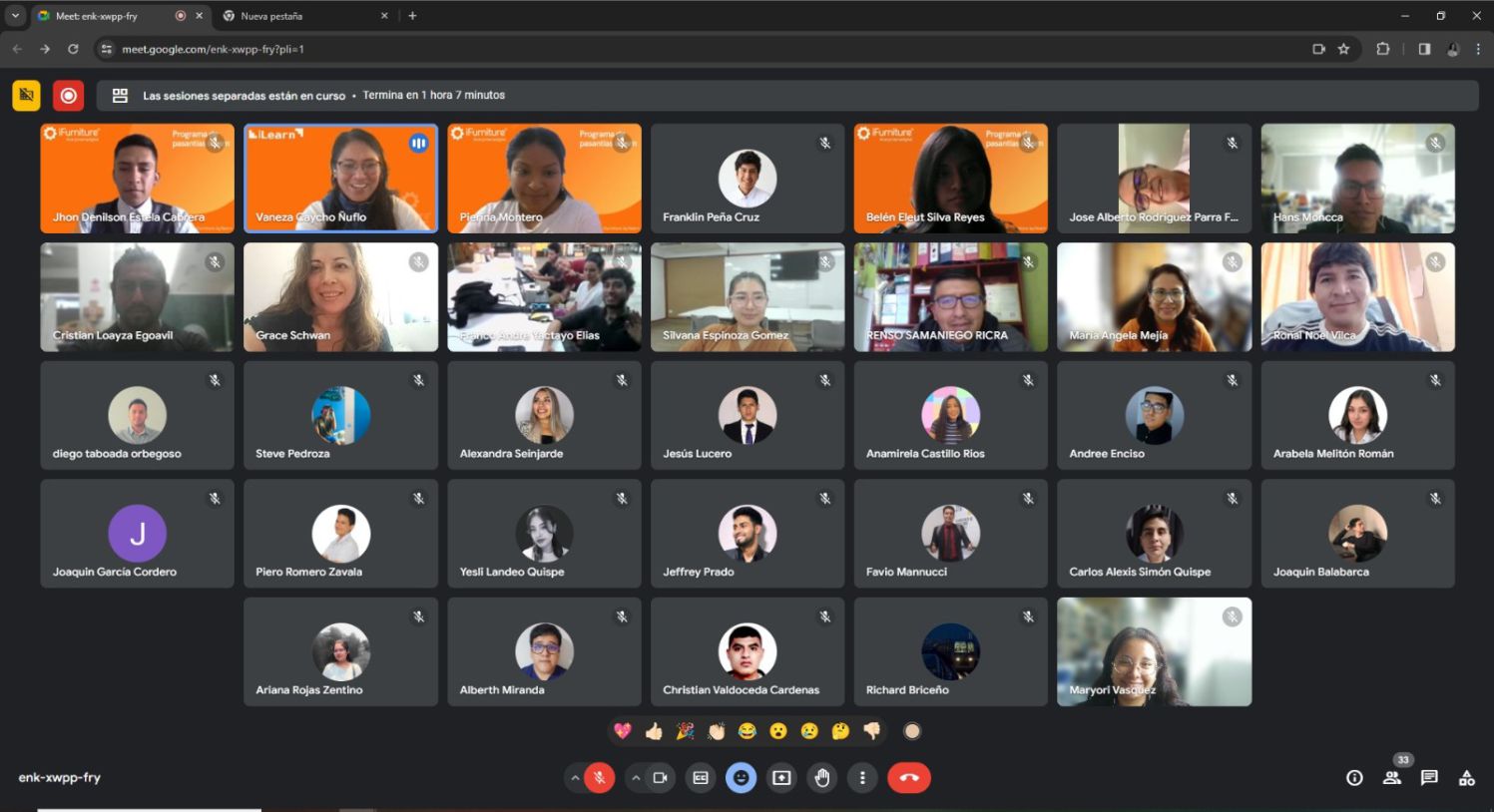
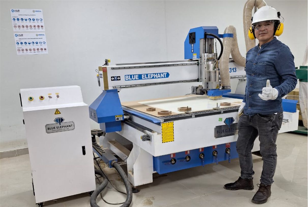
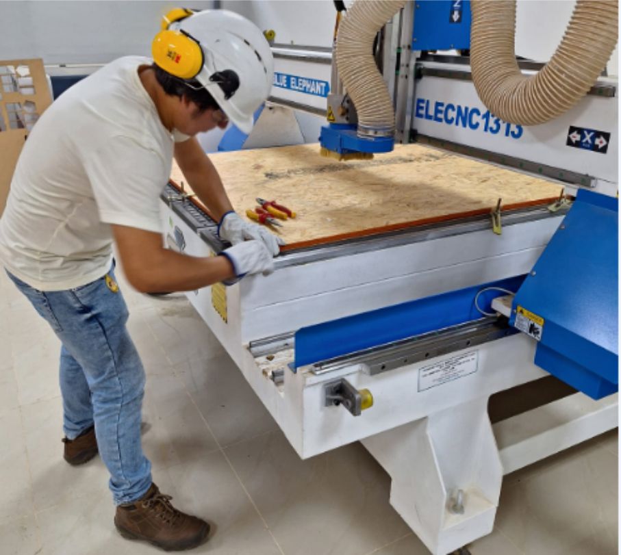
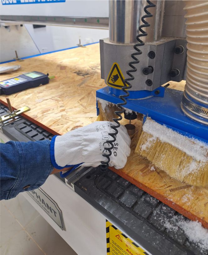
For this week's group task, the first thing we did with the Fablab Peru team was receive security training. This was necessary since we were going to put into operation a CNC Router machine, which requires expert handling and priority safety training.
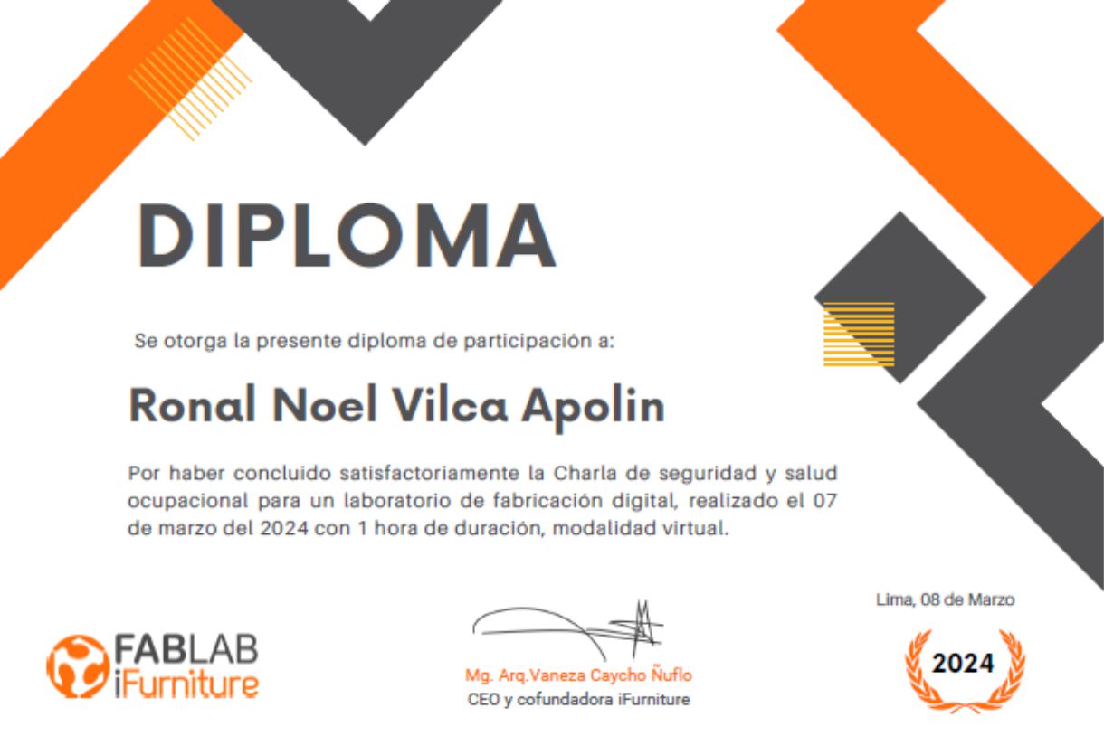
Training certificate.
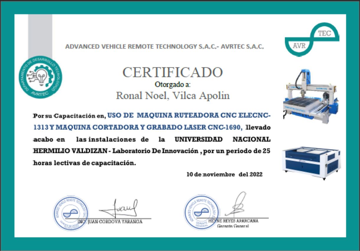
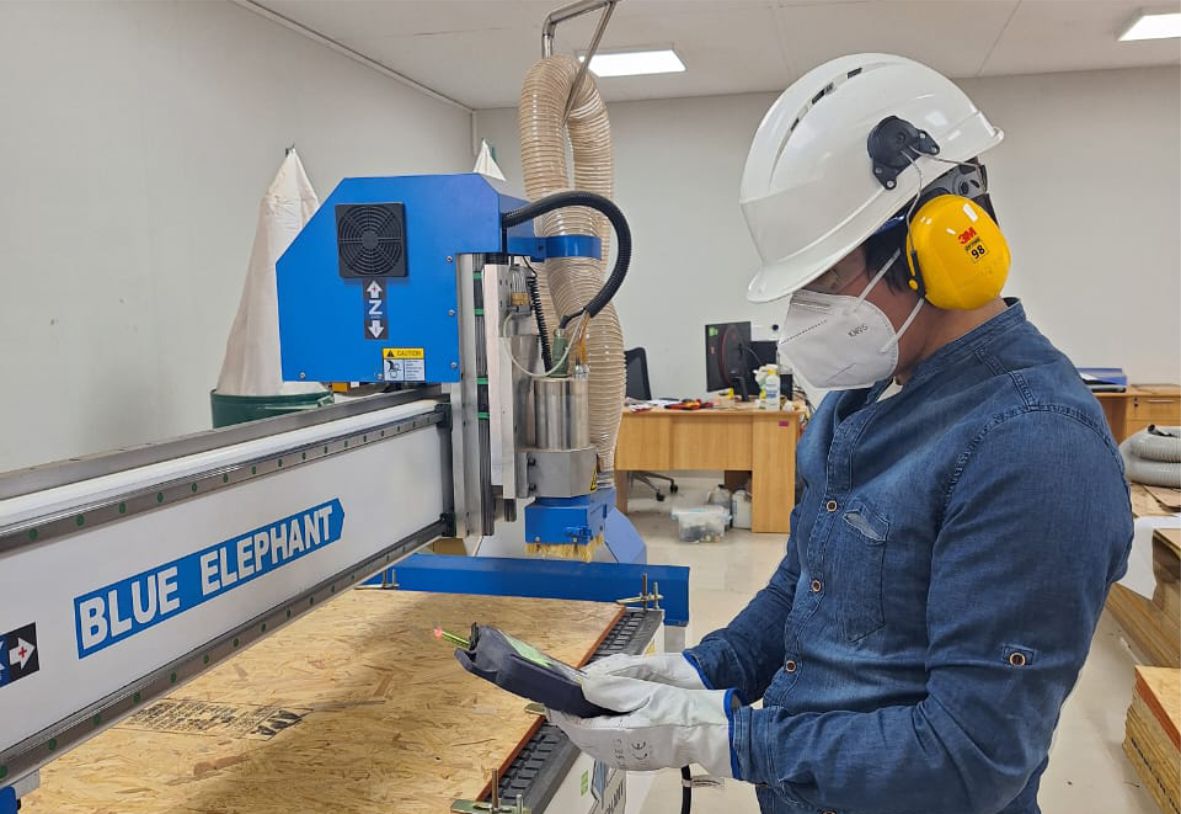
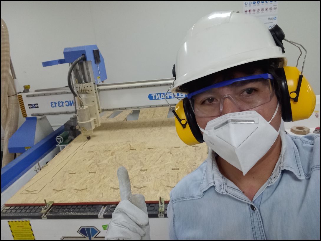
Elephant CNC router machine training.
We are equipped with everything necessary to operate the machine safely. We have the essential protective equipment, such as gloves, helmet, glasses, mask, helmet earmuffs and appropriate clothing.
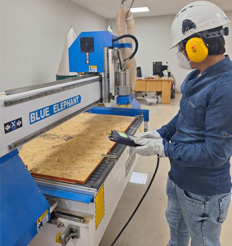
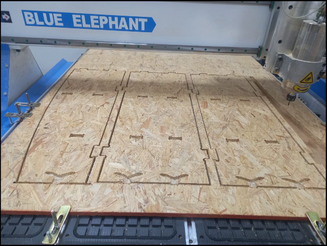
The Unheval Fablab is in the implementation process for which one of the machines it acquired is the Blue Elephant brand.
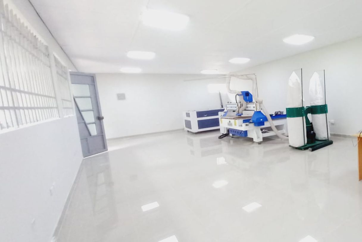
Fablab UNHEVAL CNC Router.

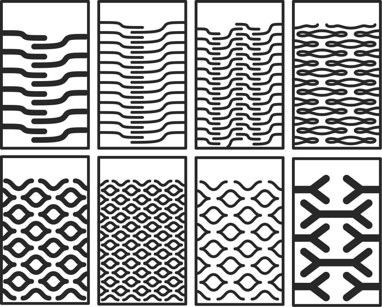
As a team we make comparisons about how our machine works, in my case I asked for support from colleagues who are in other cities in Lima specifically, they shared with me the pattern they managed for the inserts.
As part of teamwork, we make comparisons on how our machine works. In my case, I requested support from colleagues located in other cities, specifically in Lima. They shared the patterns they used for the ensembles with me through an online connection.
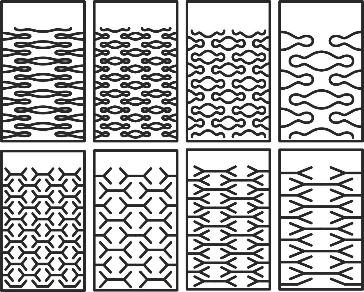
Test vectors for cnc machine.
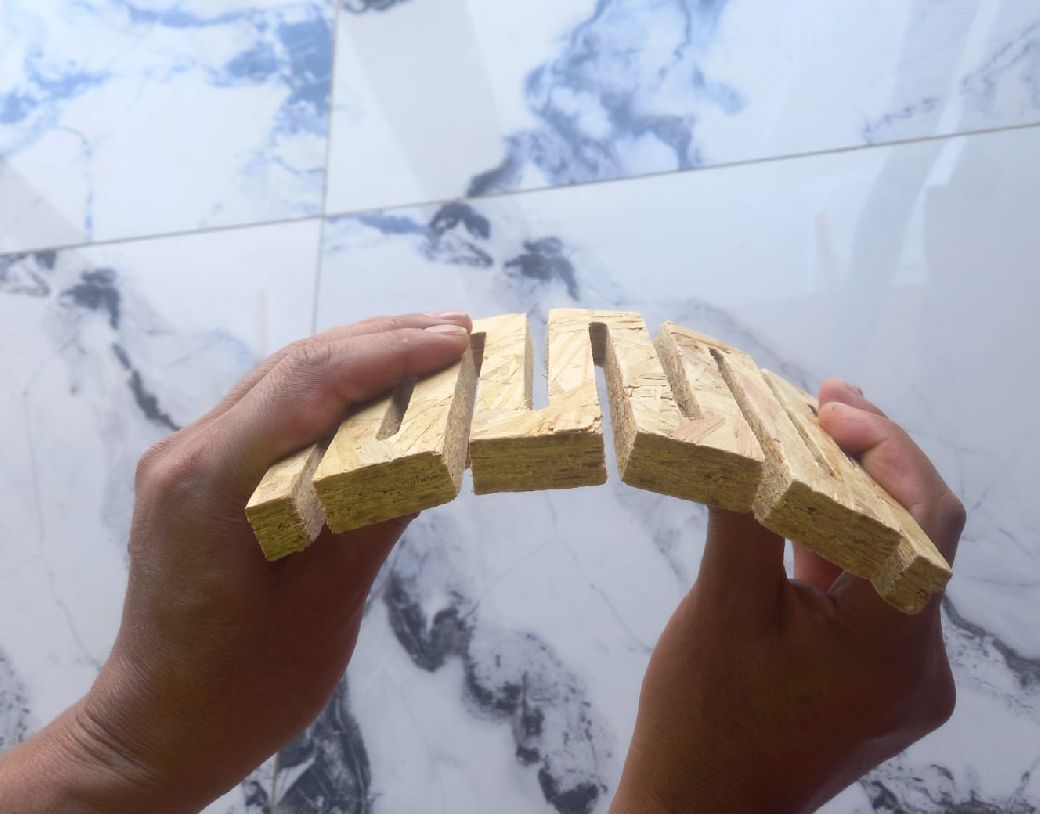
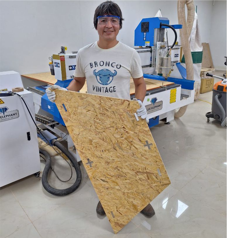
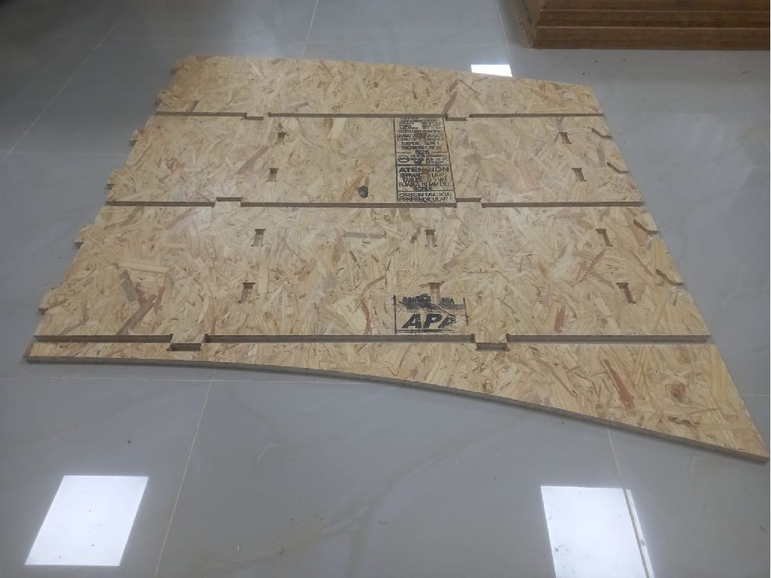
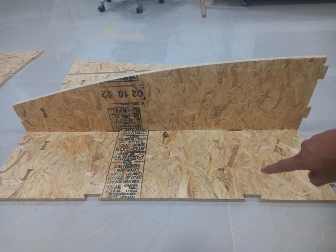
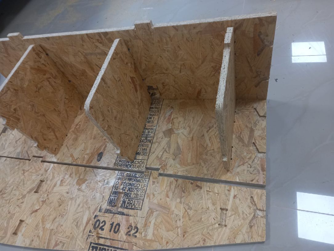
As you can see, this is the test carried out with 15 mm OSB material. Its flexibility is clearly noticeable.
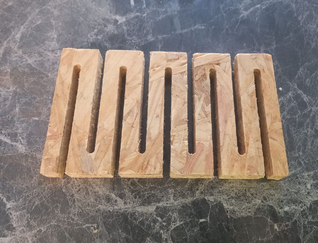
Test vectors for cnc machine.
During this week, I have learned the importance of teamwork and collaboration between all members. This becomes crucial, especially when calculating sockets, as an incorrect calculation can result in the inability to fit the pieces together, as I experienced in one of my tests. In addition, I understood the relevance of clearances and the consideration of the type of material we work with. Each material has to be worked with different characteristics in terms of cutting speed, roughing and working depth, which significantly affects the process. Always keep safety in mind as it is paramount, 'safety comes first', and it is essential to apply common sense at all times."
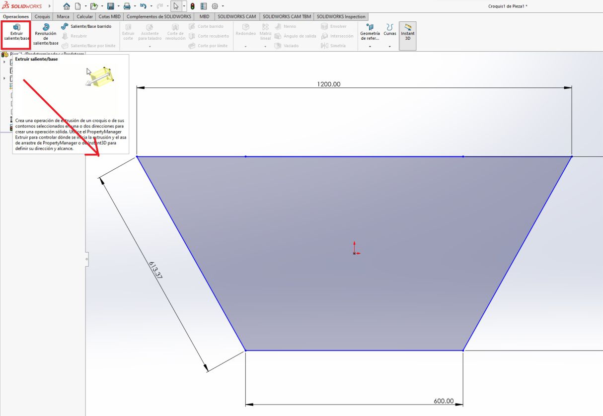
Since my first idea was to create a modular table with a trapezoidal shape, let's start with our sketch.
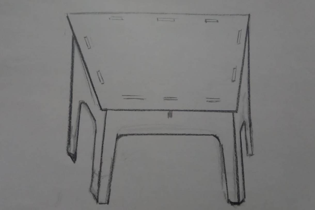
For my individual assignment this week, I used Solidworks software to design and model the parts, in this case, a trapezoidal modular table.
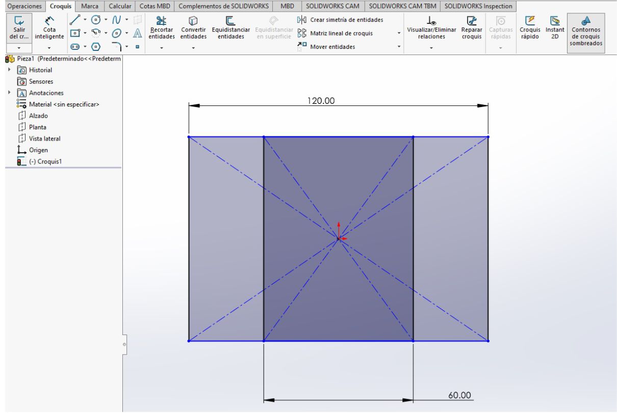
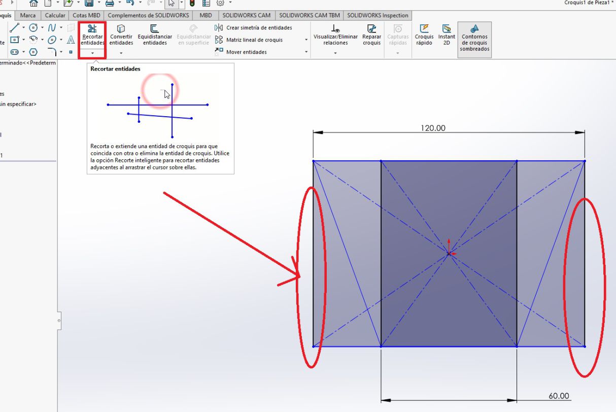
For this particular design, two geometric shapes are drawn: a square 60 cm long and a rectangle 120 cm long. This approach was chosen with the purpose of achieving a modular table with a trapezoidal shape as the final result.
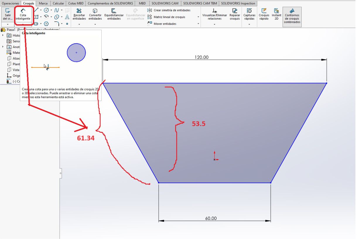
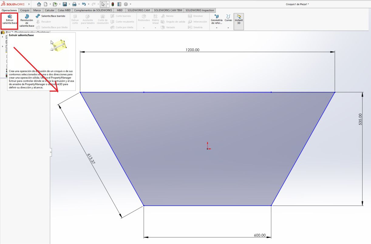
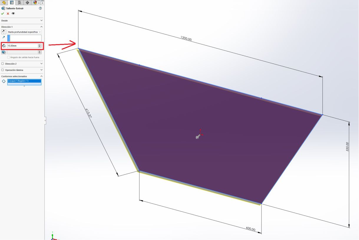
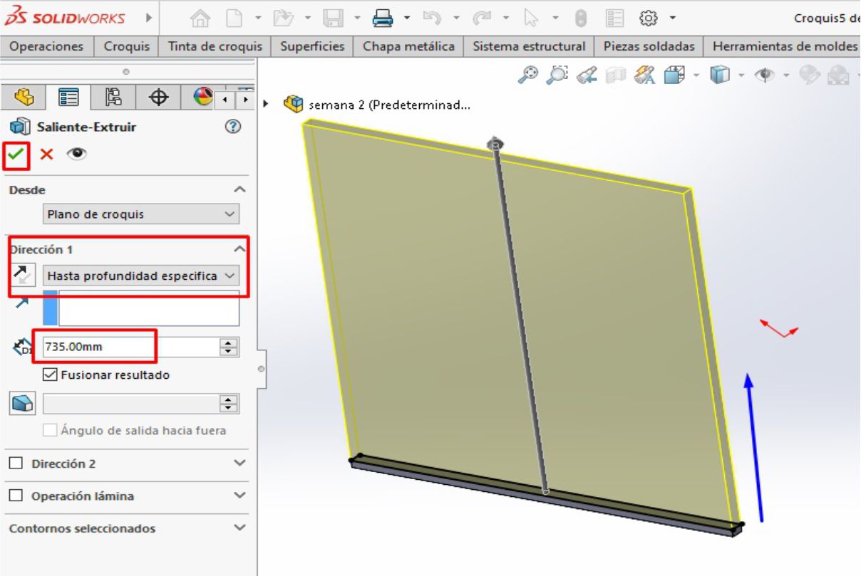
Once I had the trapezoid, I proceeded with the extrusion operation. To do this, we select the area to extrude and determine the appropriate direction. Subsequently, we add a thickness of 15 mm, which is the thickness of the material to be cut.
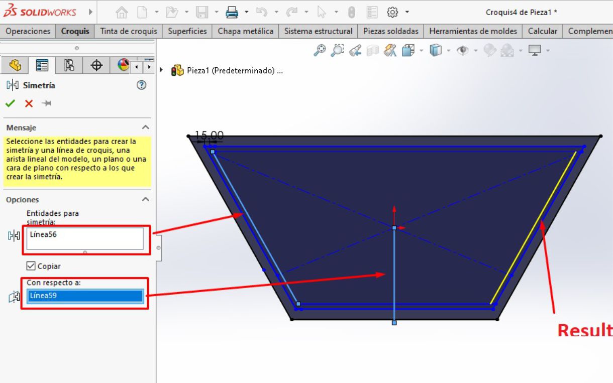
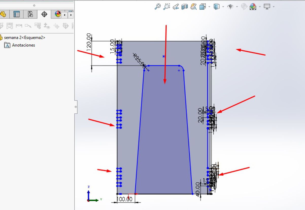
Once we have our trapezoid, the next step is to draw another trapezoid with a thickness of 15 mm on the inside of the original trapezoid. This new trapezoid is located at a distance of 40 mm from each straight horizontal side and 30 mm from the two inclined sides.
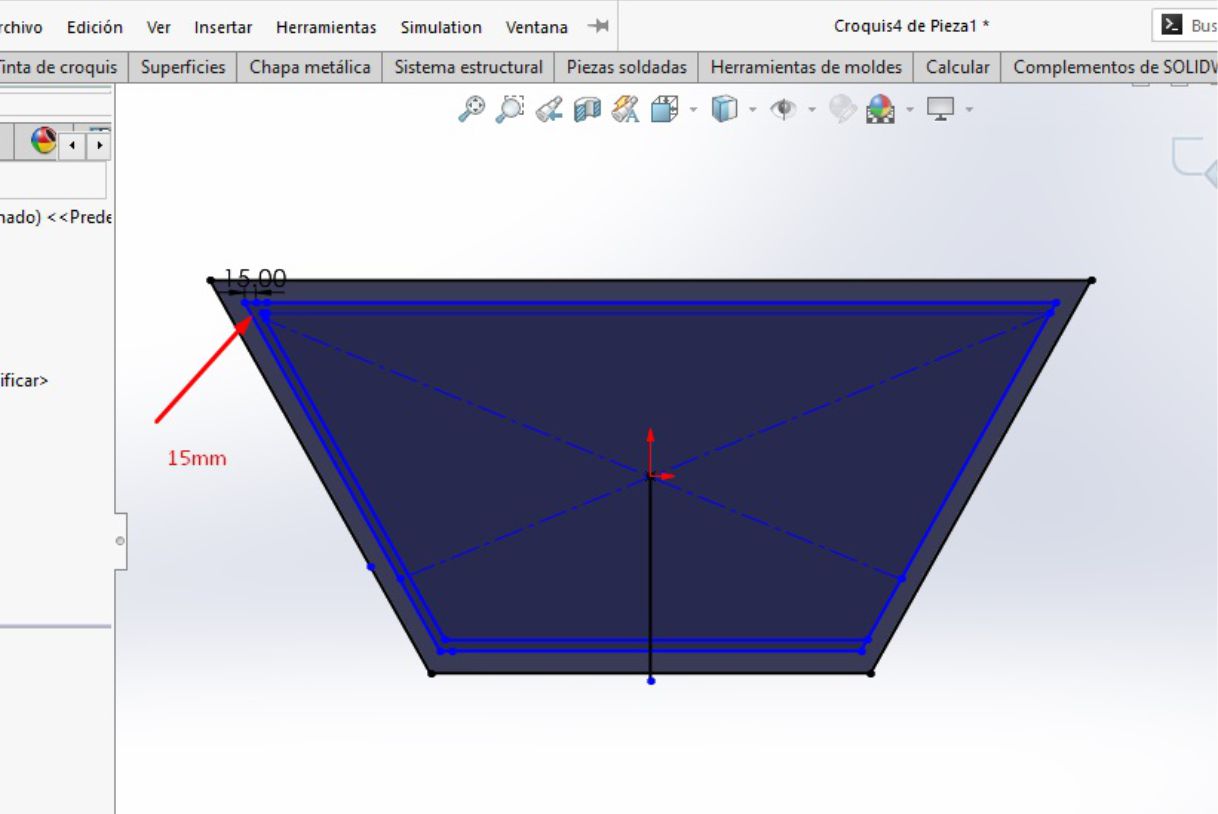
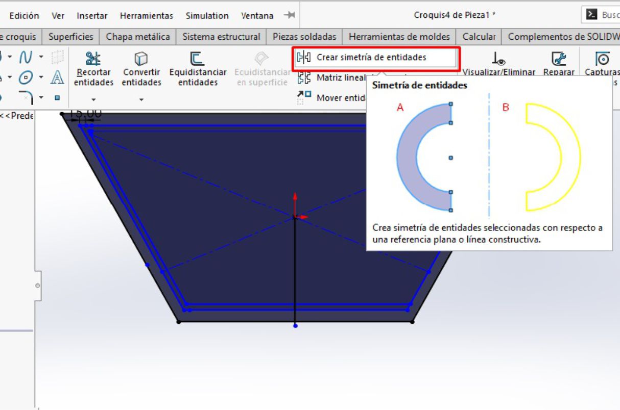
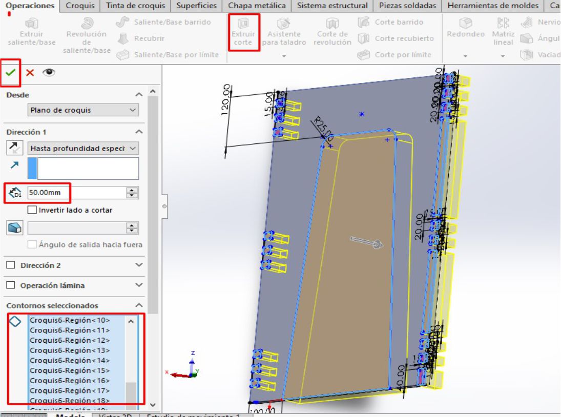
This internal trapezoid was created as a reference to locate the legs of the table and make the necessary fittings. After drawing the insert guides, the next step is to proceed with the cutting operation
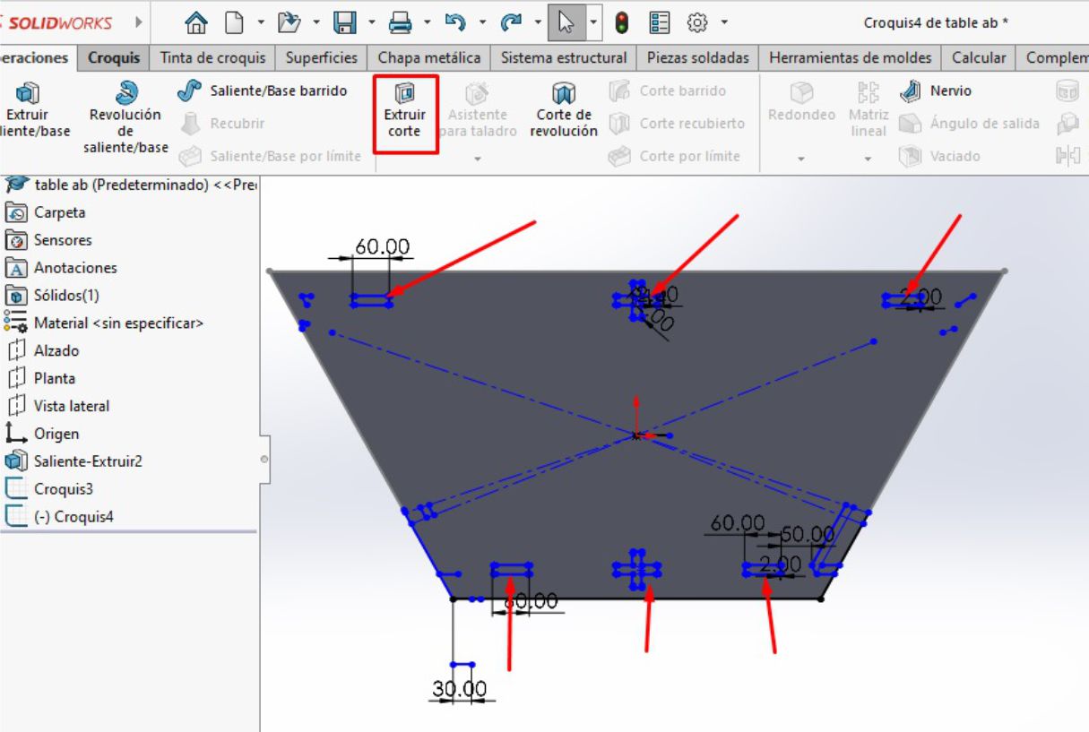
We can see how our platform turned out with the guides for the inserts.
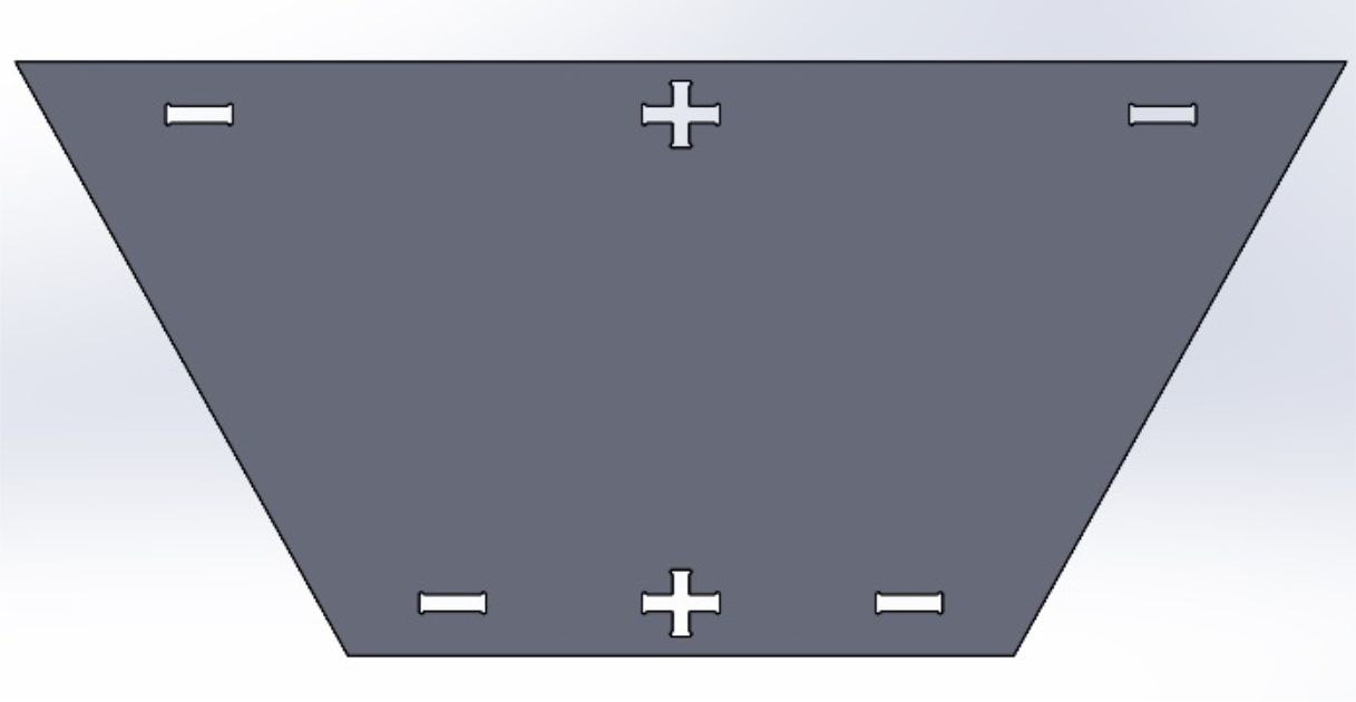
Table platform
Voy a simplificar este diseño reduciendo los pasos, ya que en la primera parte he mencionado cada paso detalladamente
To design the legs, the first step is to use the plane of the table platform as a reference, specifically the interior trapezoid, since these legs will fit into it.
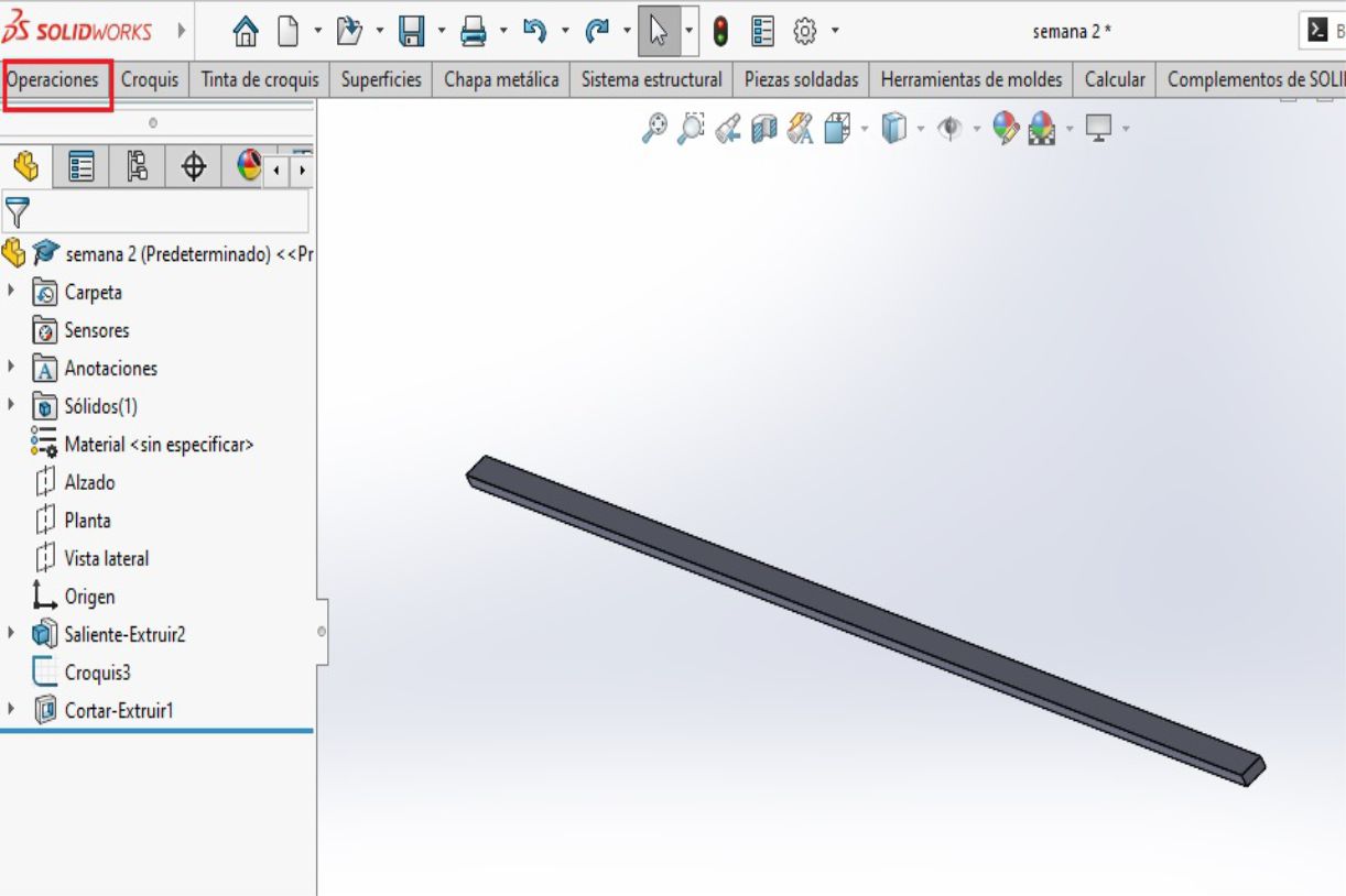
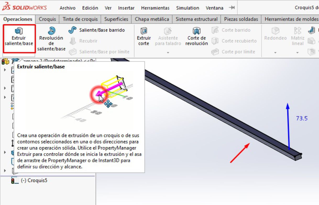
After finalizing the design of the legs, we proceed to make an extrusion with a height of 73.5 cm, according to the measurements that we have previously established.
Once the appropriate size has been determined, we proceed to make the necessary cuts and inserts to shape the legs, as illustrated in the image.
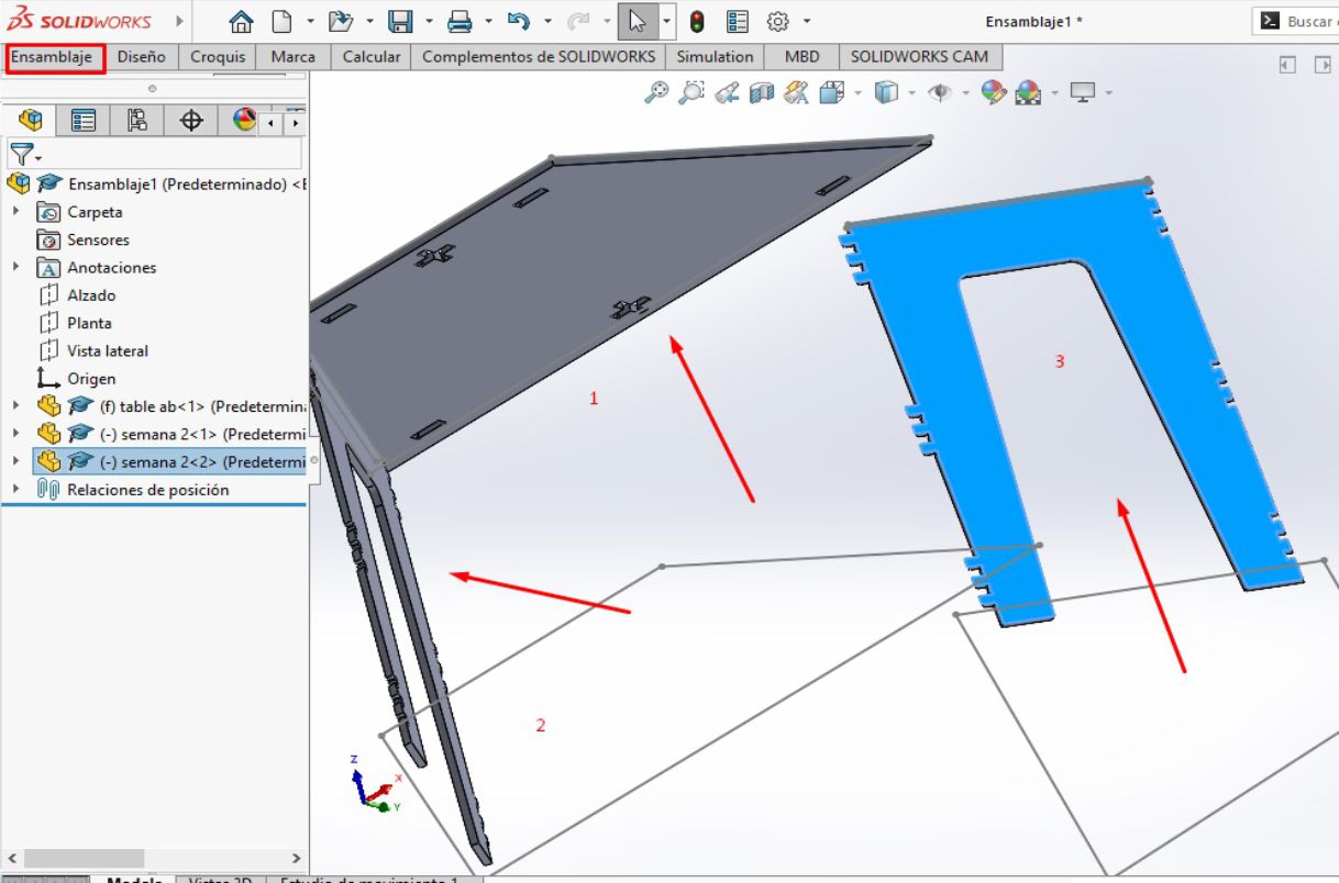
The next step involves modeling using the parts previously designed in SolidWorks. For this, we access a different work environment, specifically the assembly environment, where we insert all the relevant pieces and parts.
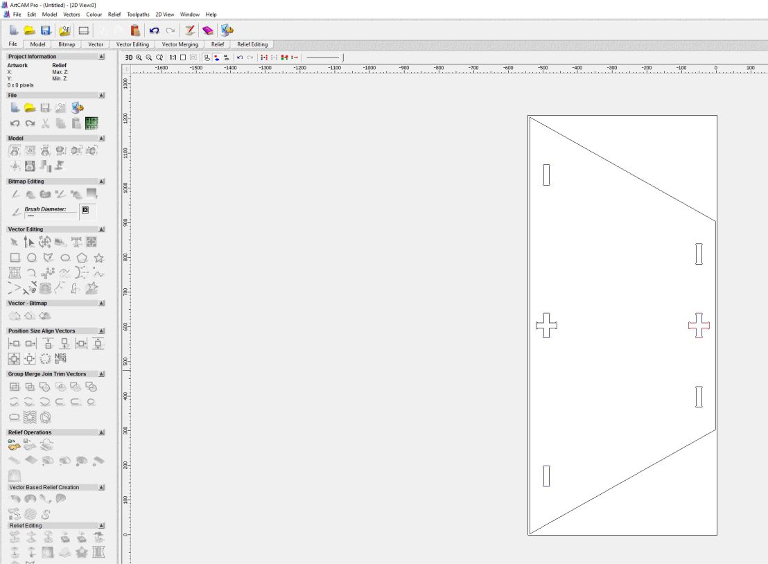
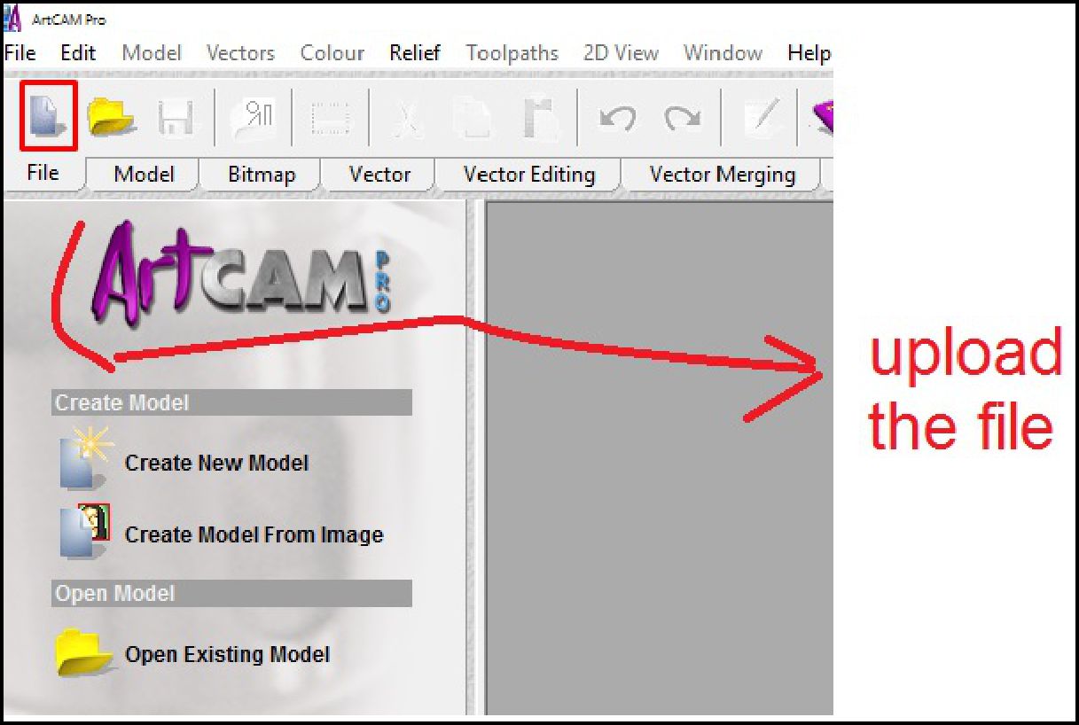
In the CAM process, I will use the ArtCAM software, which is compatible with this machine. The first step is to establish the reference of the work area and the precise location of the work point.
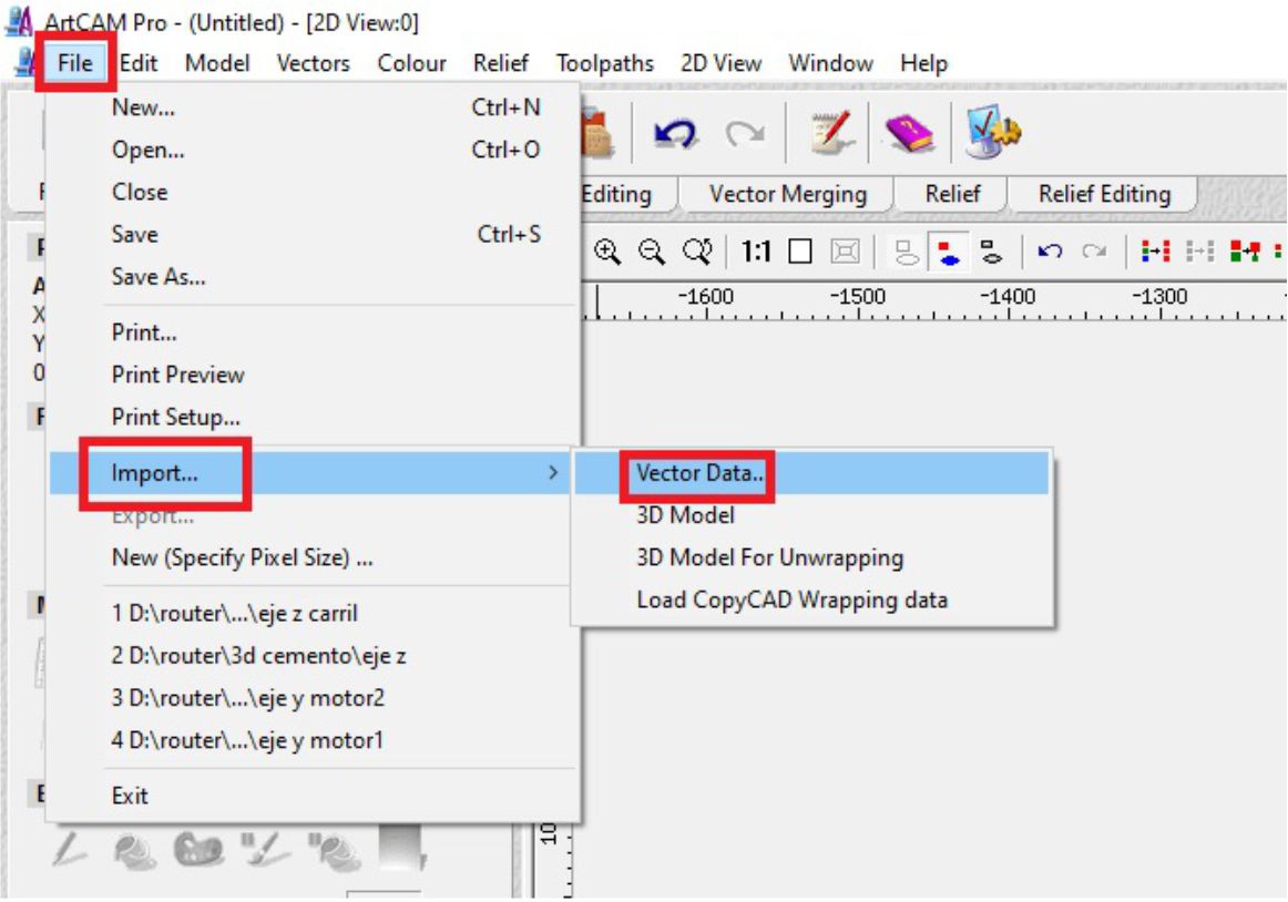
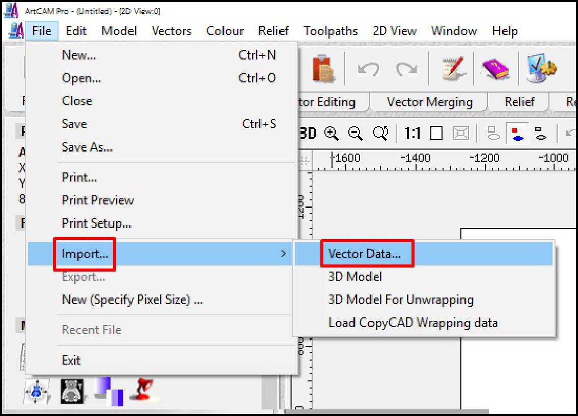
Subsequently, we go to the toolbar and select 'Files', followed by 'Import' and then 'Vector'. Next, we choose the file from the folder where it is hosted.
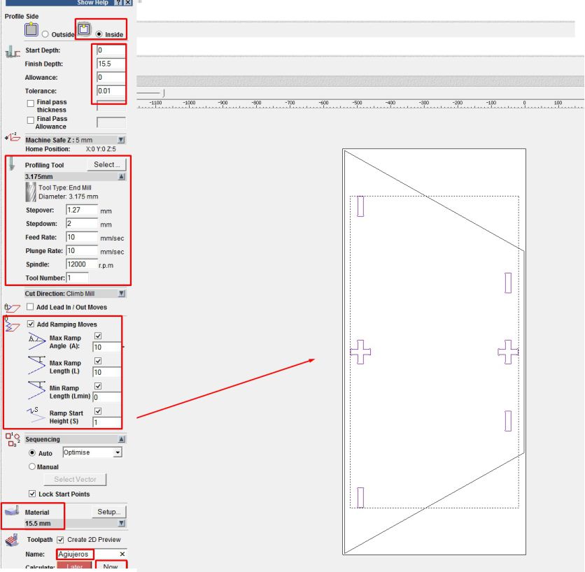
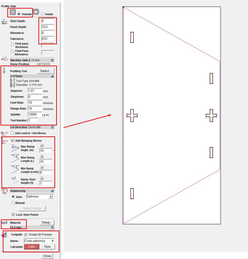
Next, we configure the roughing and cutting parameters, including the selection of the 3 mm diameter cutter, the Spindle speed at 12000 rpm, a cutting thickness of 2 mm per pass, a feed rate of 10, and exiting the work on a ramp to avoid damaging the cutter.
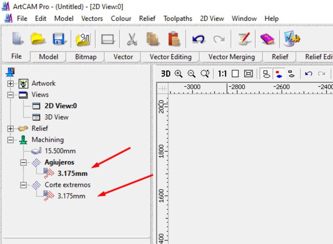
After having configured the parameters, we can observe the G codes that have been generated. There are two sets of codes: one for roughing and one for cutting respectively.
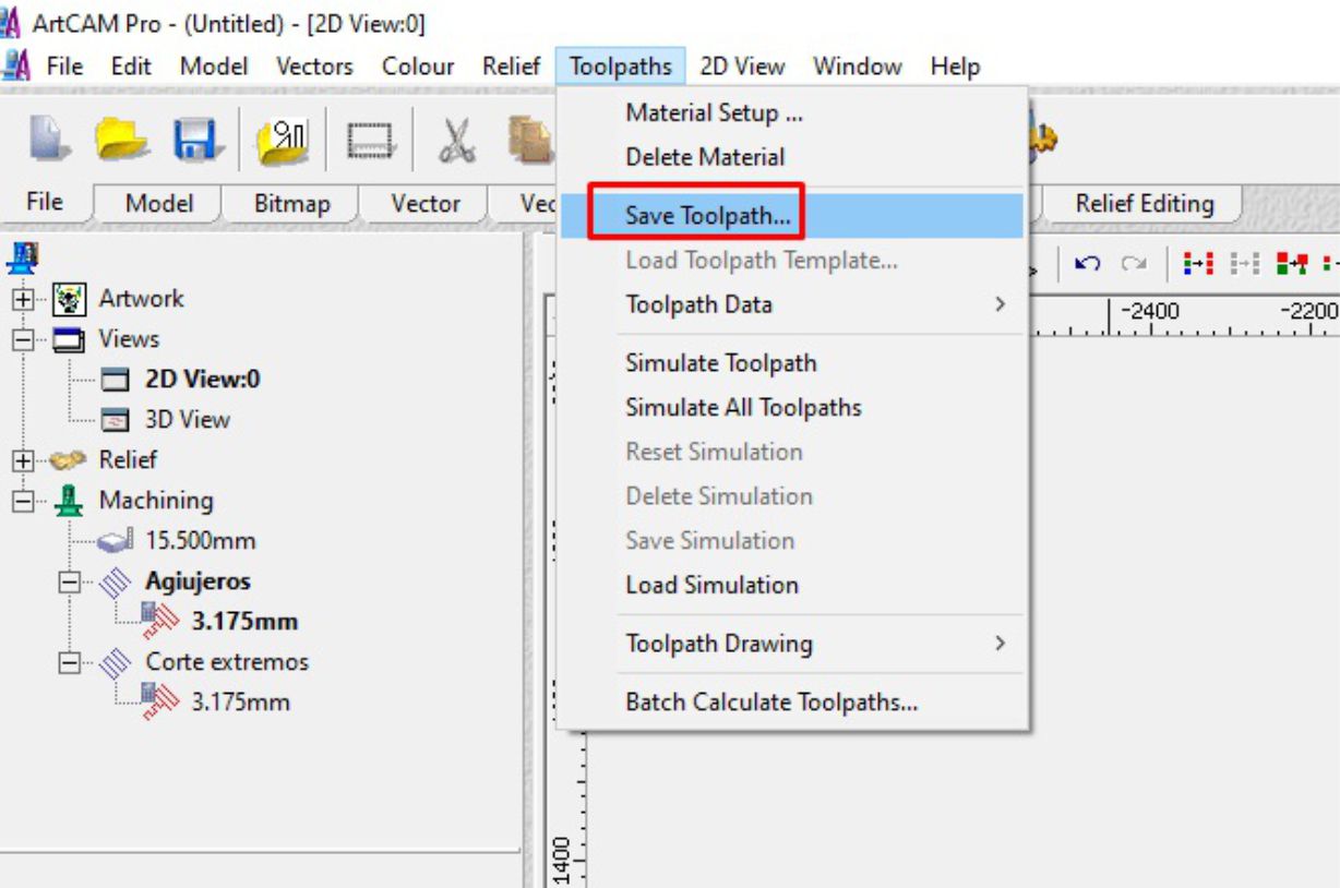
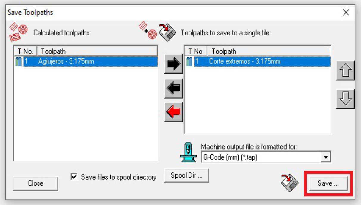
To save these files, we go to the toolbar and select the "Toolpaths" option. Then, we save the files to a USB device.
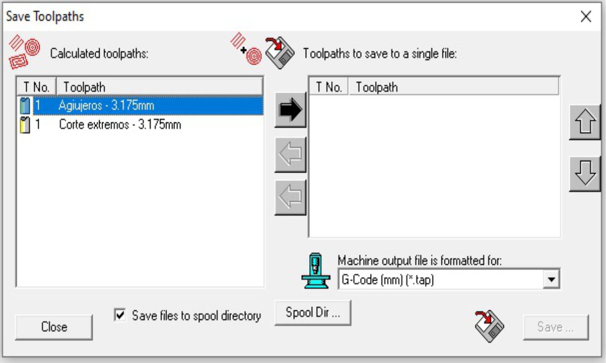
Immediately, a window will appear where we will select the generated files one by one, individually.
To begin the machining process, the first thing to do is fix and secure the material. Once set, the next step is to define the 0.0 point on the "X" and "Y" axes.
The next step involves calibrating the material using an appropriate part and tool, which will be essential to optimize the process at each stage.
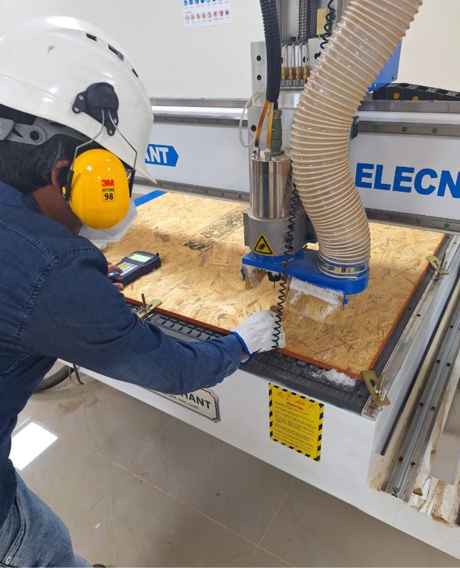
To begin the machining process, the first thing to do is fix and secure the material. Once set, the next step is to define the 0.0 point on the "X" and "Y" axes.
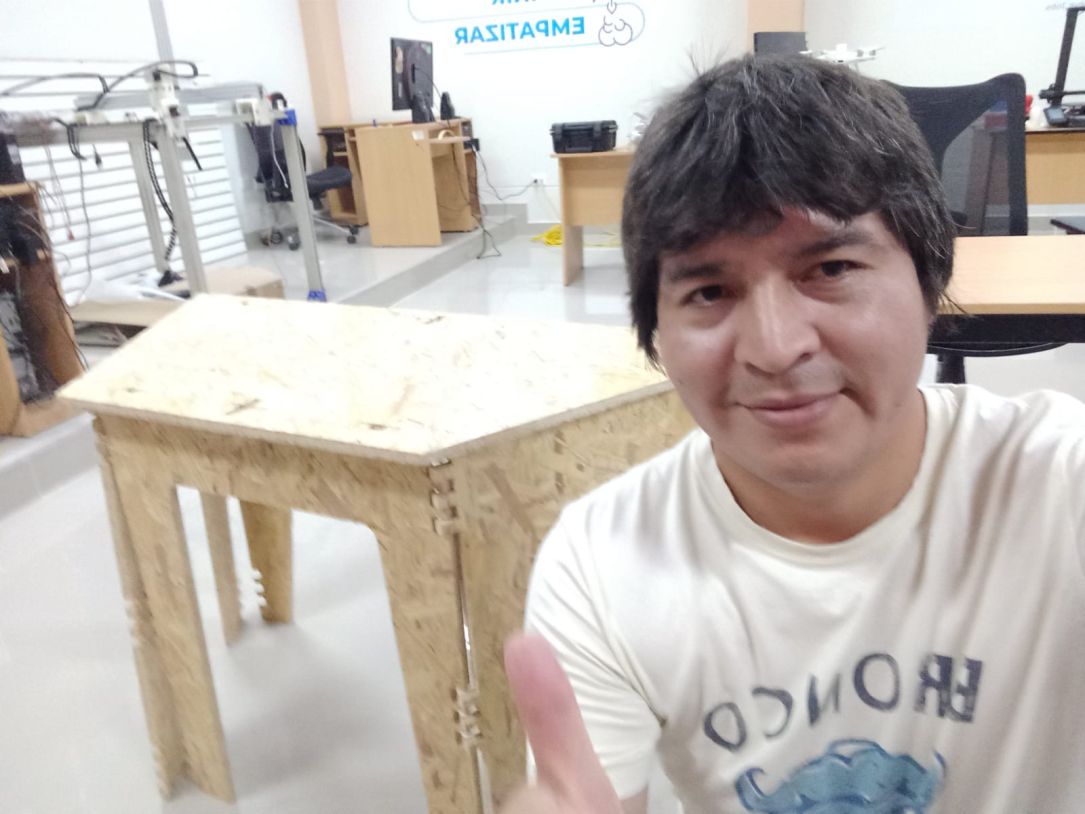

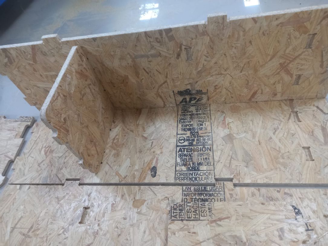
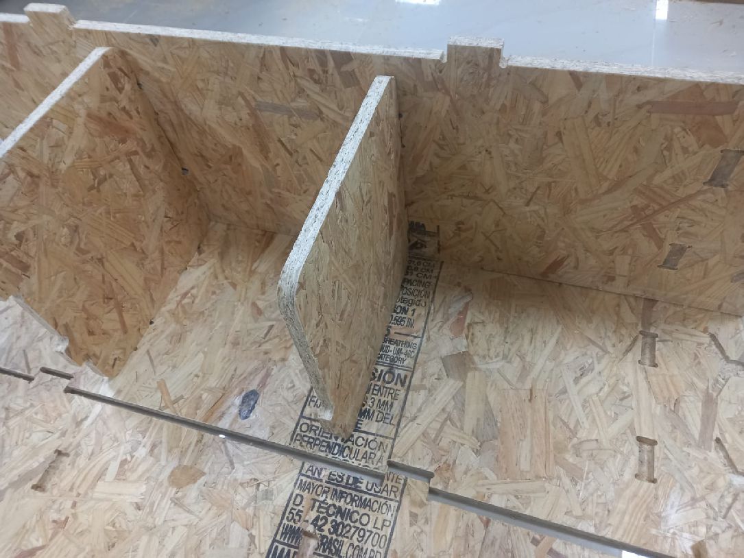
In this example of making a folding table, I made a mistake in the Gcode generation. Originally, the leg joints were designed to cut on the outside of the image, but I mistakenly programmed them to cut on the inside of the design. This caused the pieces to not fit together as expected. This work was done using ArtCAM
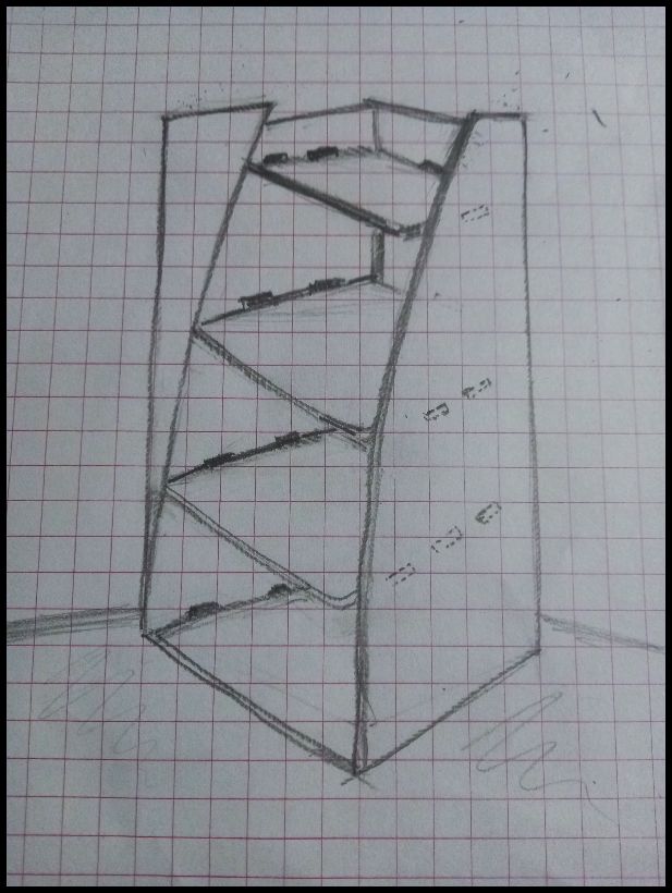
To design this shelf, I started by making a sketch of what I wanted my furniture to look like, using freehand drawing techniques.
For design development, we used Sketchup software, as shown below. Initially, it was created in two dimensions (2D), where the dimensions and general layout of the shelf were outlined.
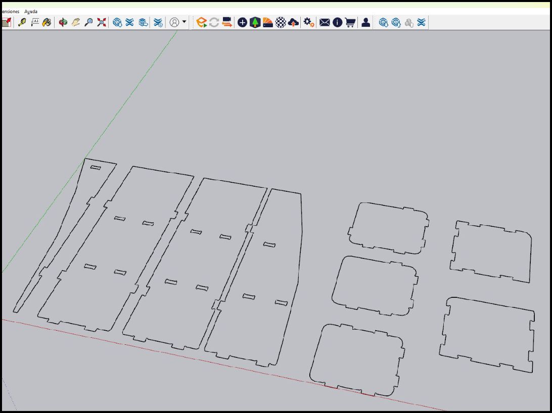
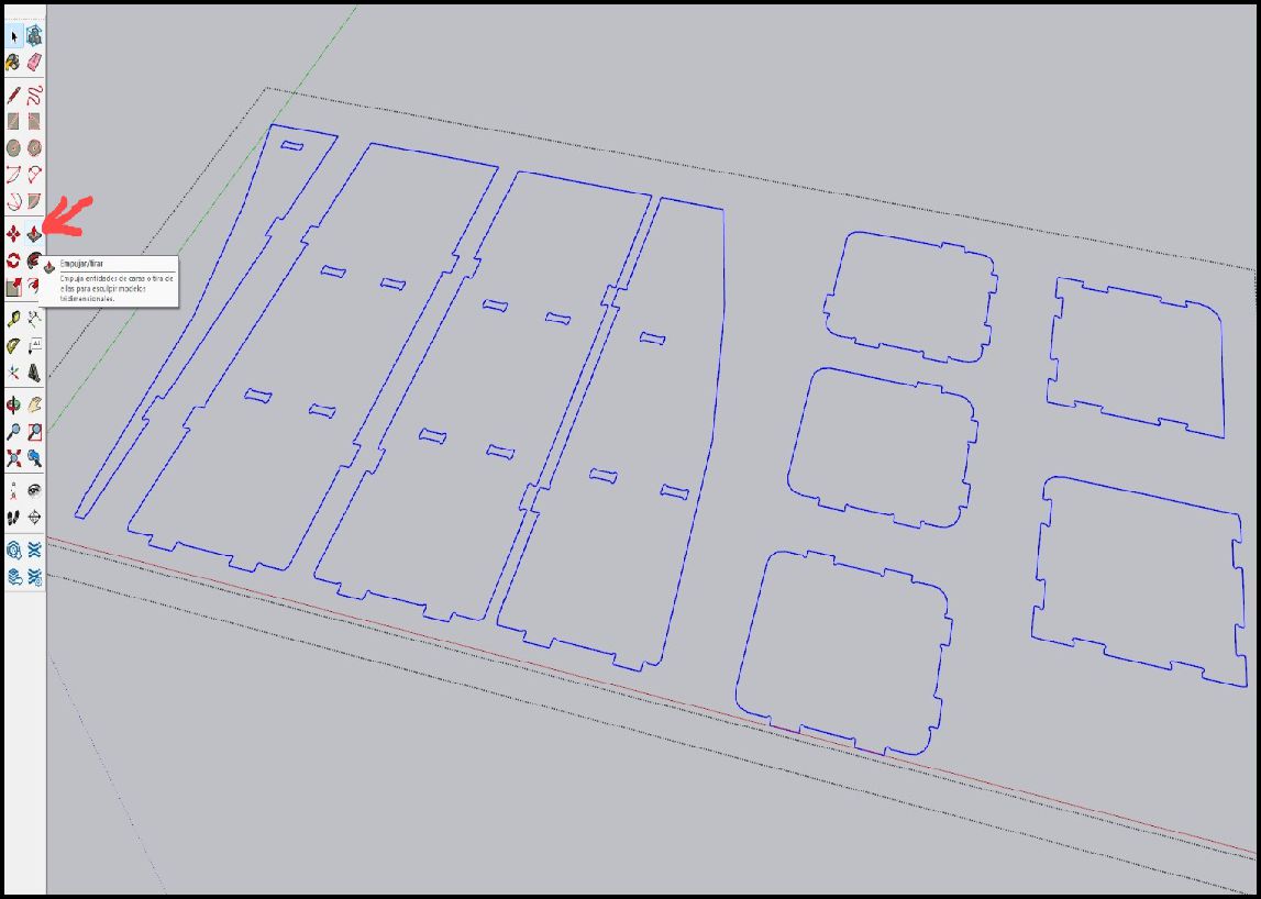
The process then continues in 3D, where the designed parts are extruded for volume and depth, allowing the shelf to be visualized in its full three-dimensional form.
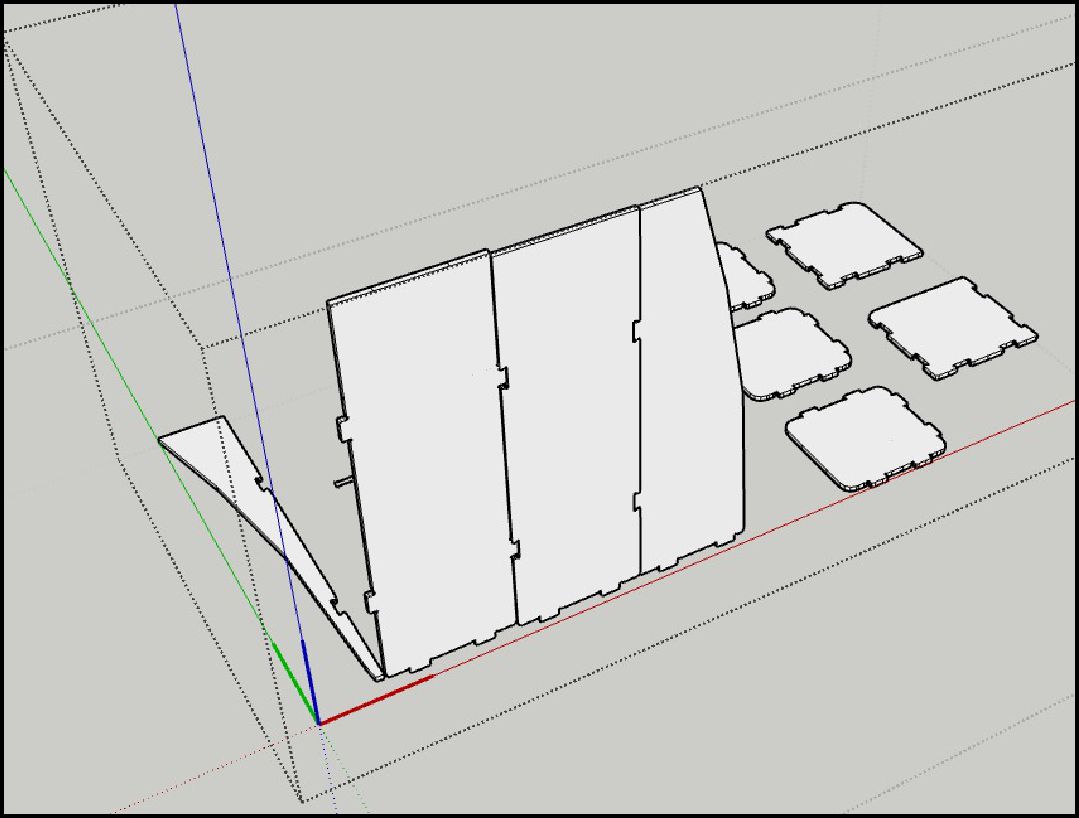 -
-
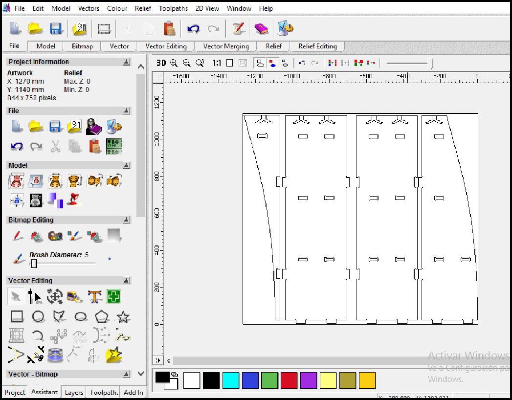
Once the design phase was completed in Sketchup, we proceeded to open the development environment in Artcam. In this software, we import the file that we had previously exported from the design. This allowed us to start working with the CNC machine to carry out the physical production of the shelf.
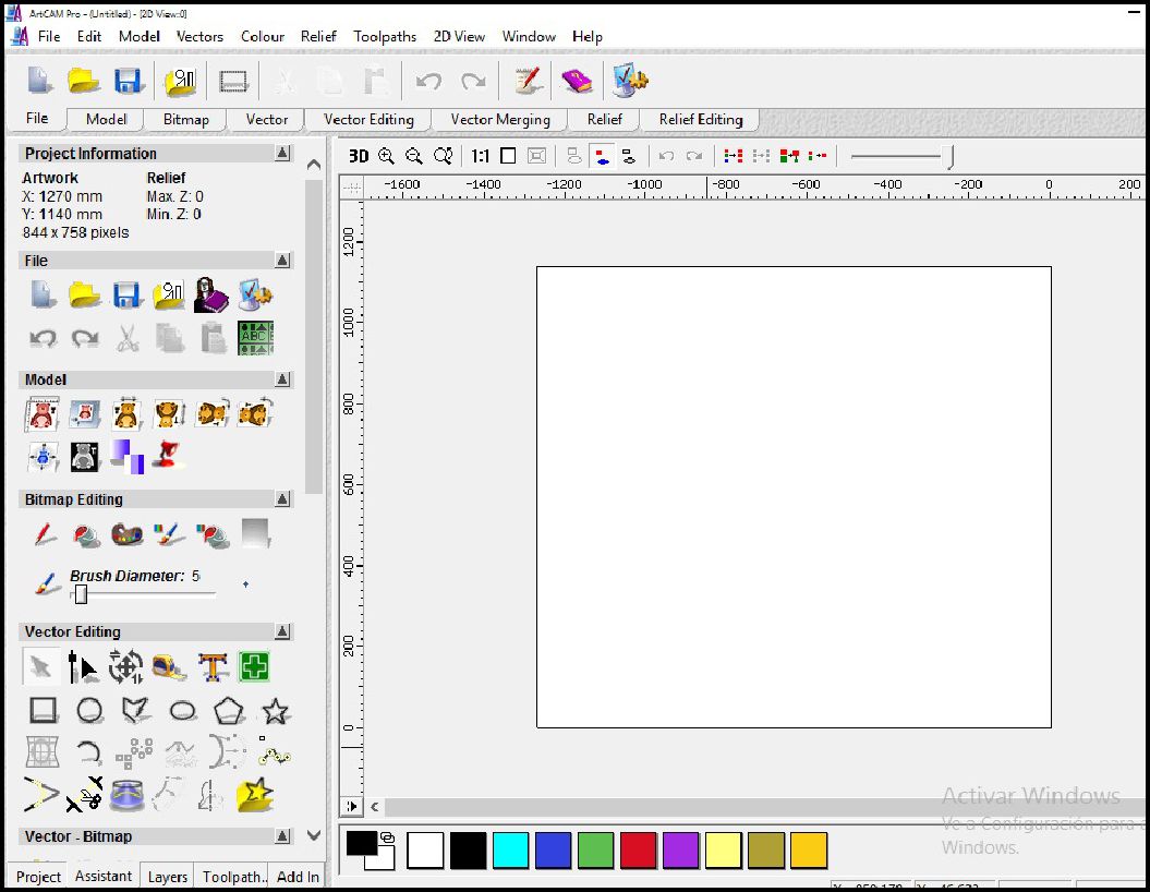
In this stage, we import the file that we have previously generated in Sketchup, which is in DXF format. This action allows us to start the configuration process necessary to prepare the design and adjust it according to the specifications required for its manufacture using the CNC machine.
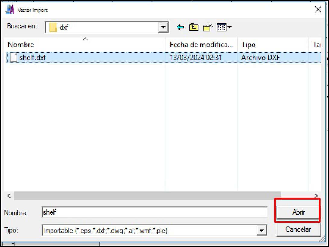
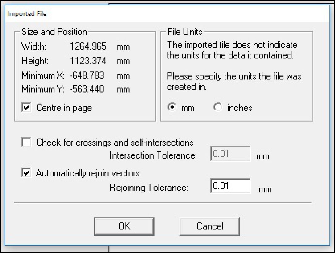
When we import the file, the software will ask us to specify the units of measure and the import position. This step is crucial as it determines how the design will be interpreted and represented in the CNC machine software working environment.
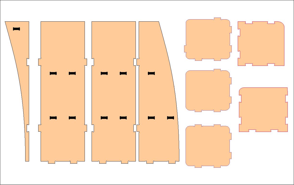
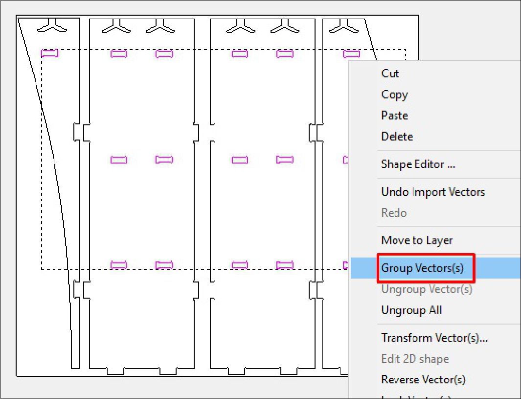
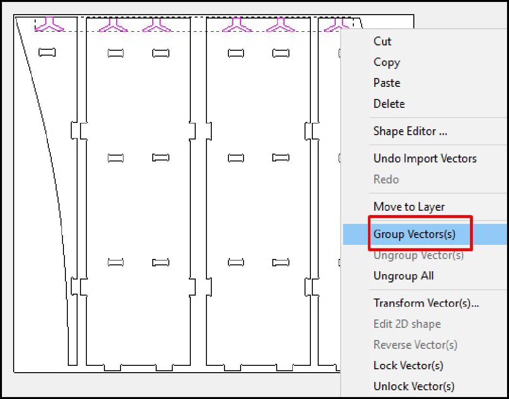
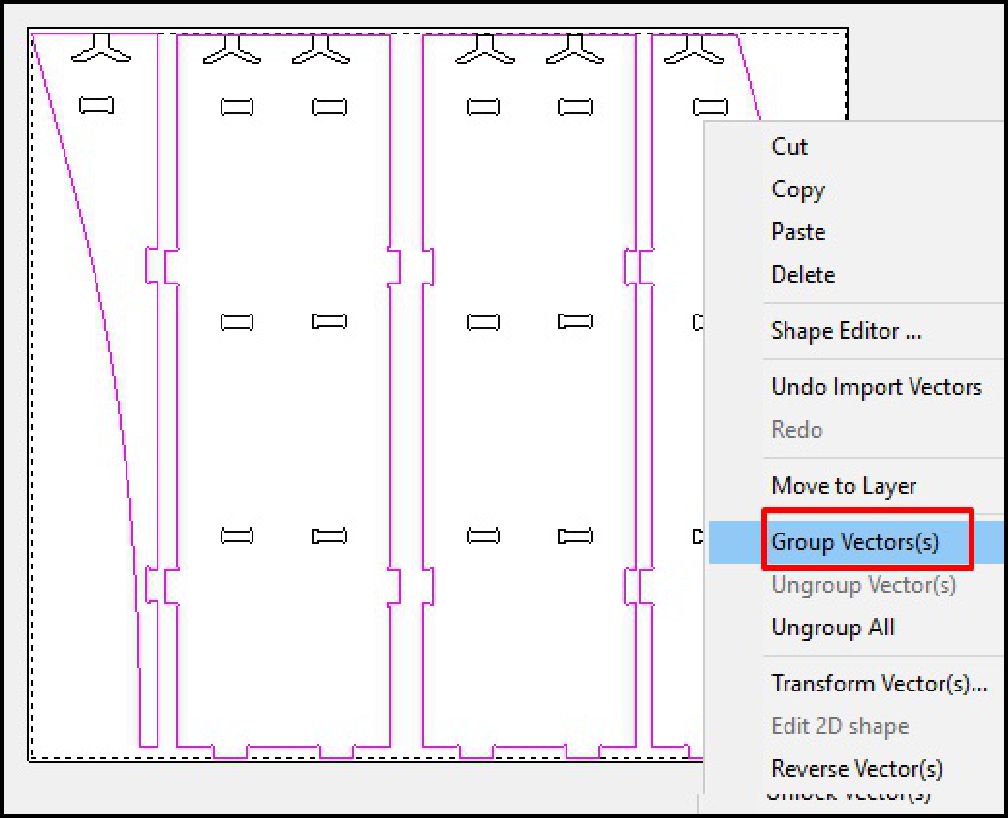
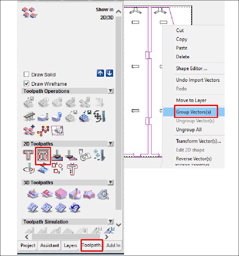
Once the file has been imported, the next step involves grouping similar elements to define the type of work that will be carried out by groups, as is the case with cutting and roughing in this project. This organization by groups facilitates the planning and execution of machining operations, allowing a more efficient and precise approach in the manufacturing of the design.
As a last step, we configure the type of cut, the cutting depth, as well as the roughing and the tool to use. In this case, with a tool diameter of 6 mm, we adjust the cutting parameters according to the specifications required for the project. This includes defining the cutting speed, feed rate and other settings necessary to ensure accurate and efficient machining of the design on the CNC machine.
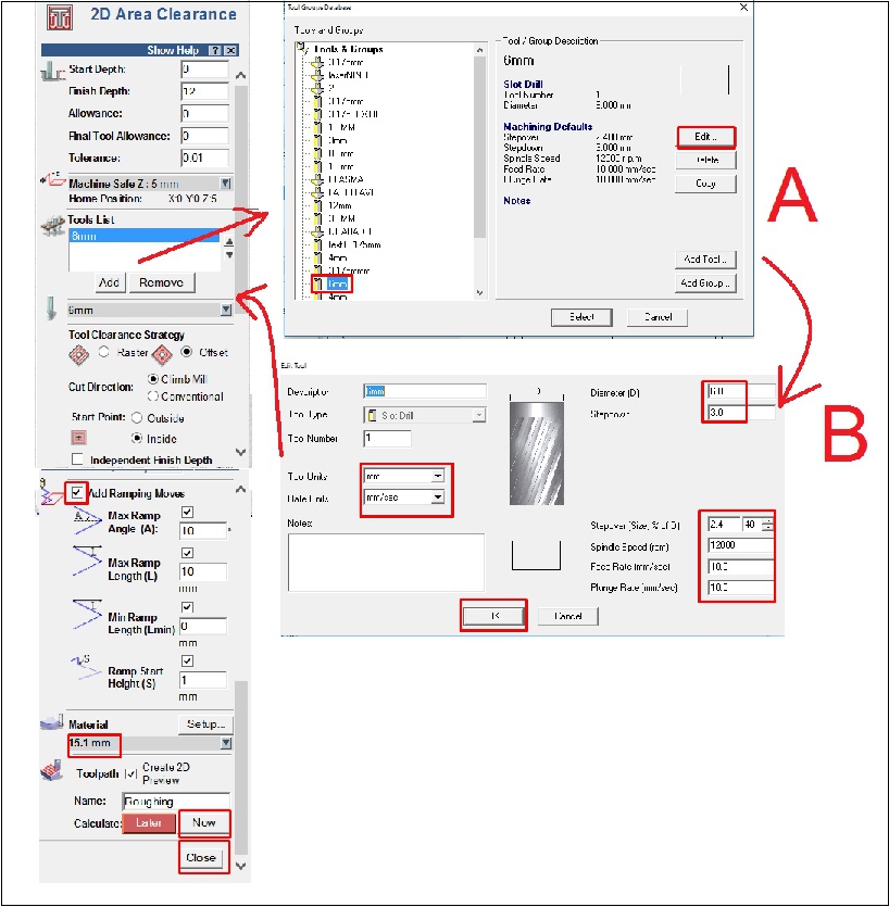
During the machining process, we use a tool with a diameter of 6 mm. We set the spindle speed to 12000 rpm, the feed rate to 10 mm/s and the plunge rate to 10 mm/s. These settings are adjusted to ensure accurate and efficient machining of the design on the CNC machine.
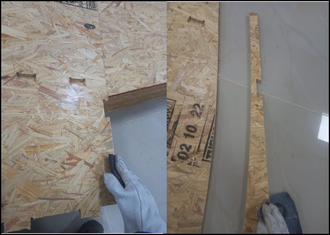
Once all the pieces have been cut, the next step is to sand away any excess chips to achieve a smoother, more refined finish. This sanding process is crucial to eliminate any irregularities on the surfaces of the pieces and guarantee a final result of high aesthetic and functional quality.
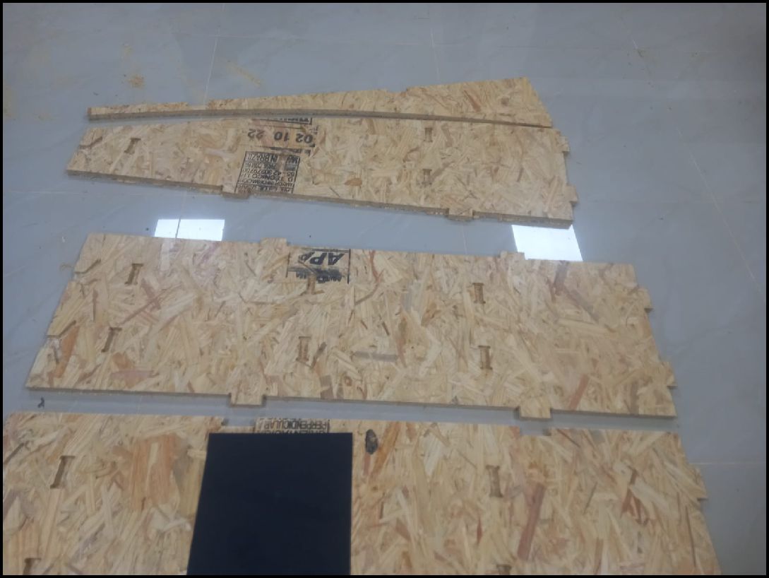
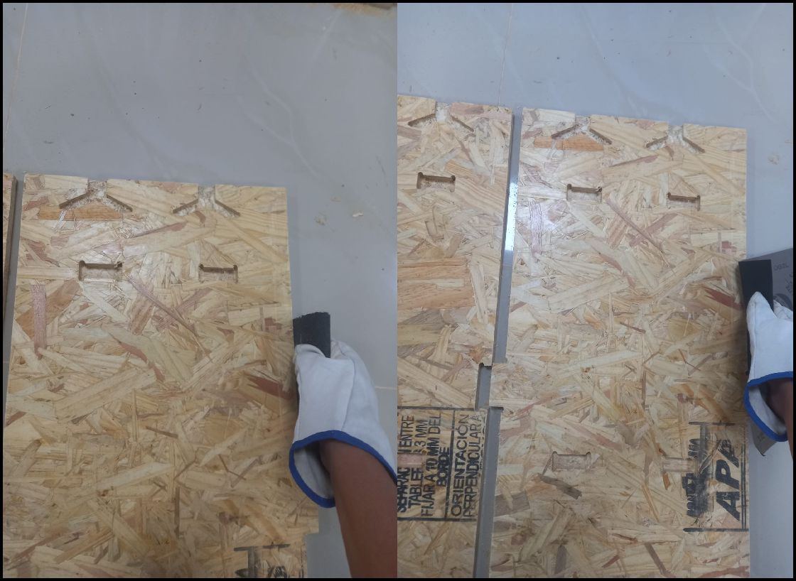
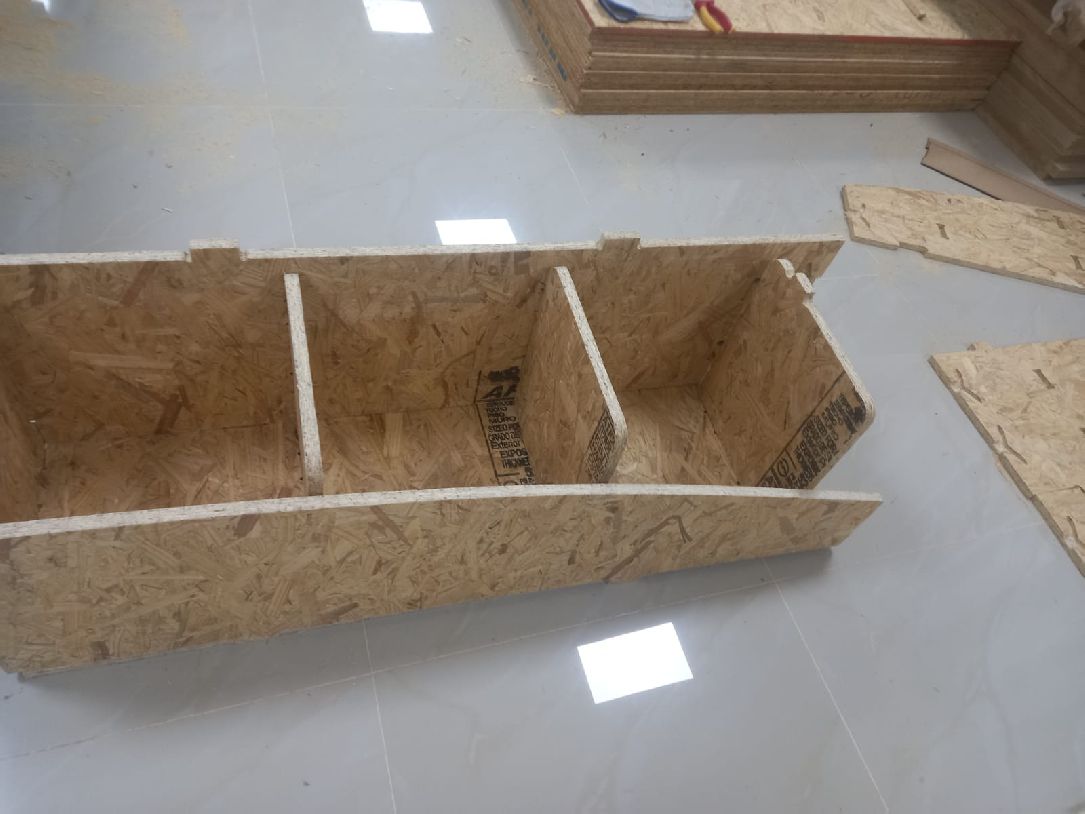
The image shows a clean process, with all the parts ready to be assembled as the next step
We started assembling the first and second pieces, and the process is going well. The pieces fit perfectly and the result is excellent.
We can also see the third and fourth pieces, already assembled, and the project is taking shape as initially thought.
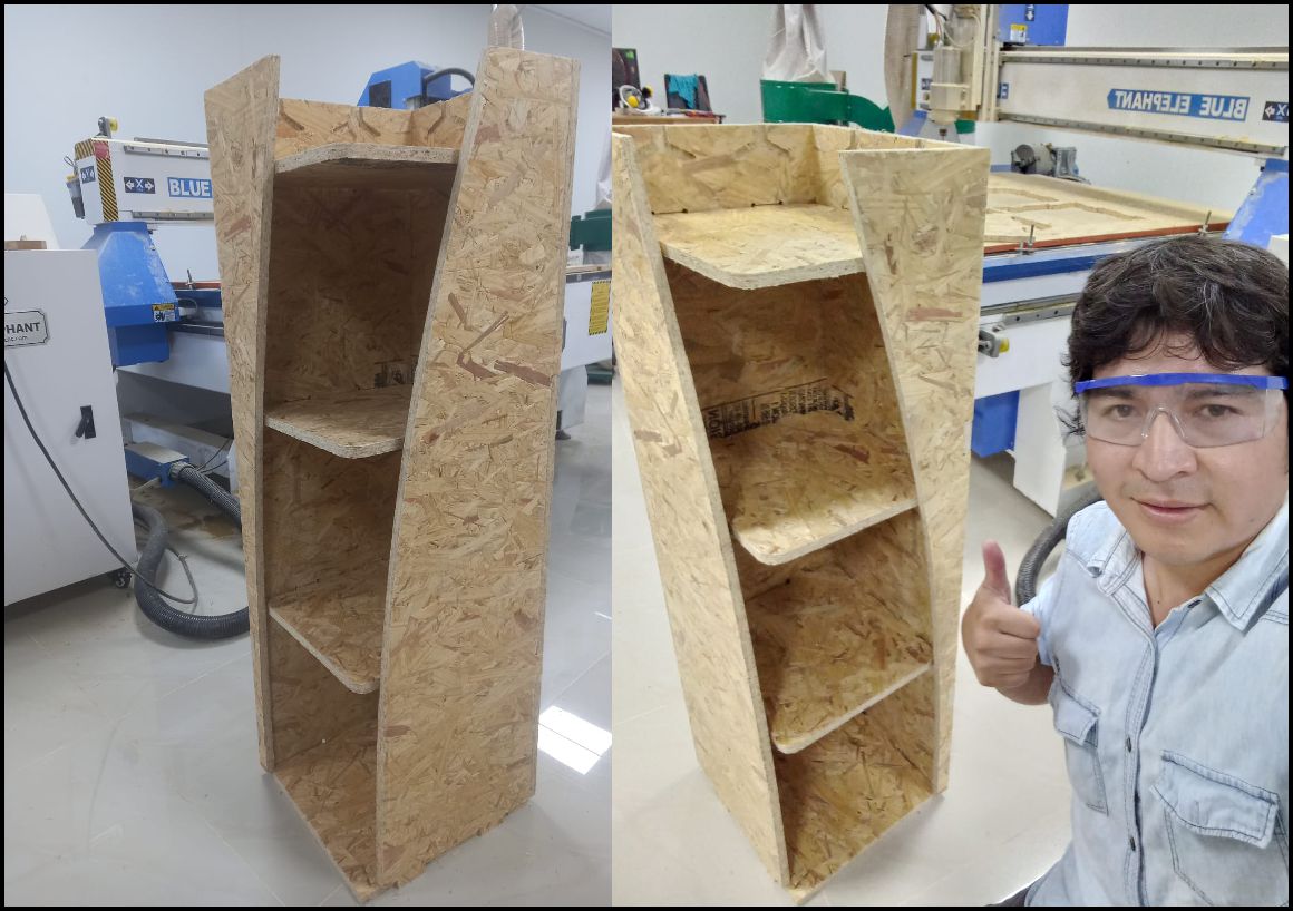
Finally, we placed the missing piece and immediately you can see how the shelf takes shape and looks great.
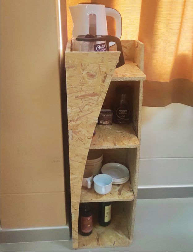
This image shows the shelf fully finished and in use. It was designed to display projects and trophies, as well as serve as a space to place coffees. Everything is in order and serves its intended purpose, so it will remain in use for this purpose.
This week has been incredibly enriching in terms of learning. I have acquired new knowledge that I was able to apply after the class, such as the ability to make precise inserts and perform calculations accurately, working with Elephant 1313. In addition, I have learned to identify and address possible errors before starting the machining process. My mistake was testing the parameters of another machine with mine, I understood that each machine operates with its own parameters. I am excited to put this knowledge into practice and continue growing in my professional career.
Development of custom electronic boards with CNC Router.
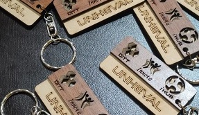
Development of personalized keychains and ornaments with CNC Laser.
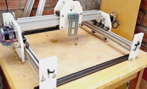
Development of custom machines "Desktop CNC Laser.

Huánuco is a Peruvian city, capital of the district, province and department of the same name in the north-central area of the country. The city has a population of 235,529 inhabitants. .